
Port ( A : in STD_LOGIC_VECTOR (2 downto 0) Īrchitecture dataflow of FULLADDER_VIATRUTHTABLE isĭataflow architecture has when-else statements that are very handy when coding with truth tables. And generally speaking, when we are dealing with multiple inputs of the same kind, using vectors saves us a lot of complexity. The first one will be the SUM, and the second one will be the CARRY. And the output vectors will have two slots. We can easily assign two vectors, one to inputs and one to outputs.
#Serial adder vhdl full
The reason is that since we are using the truth table of the full adder, we have three inputs and two outputs. We will declare the entities as vectors.īut why? Why not declare each input/output separately? The entity-architecture declaration for the VHDL code of a full adder will have only one difference.

Since this carry is not added to the final answer, the addition process is somewhat incomplete. The half adder gives out two outputs, the SUM of the operation and the CARRY generated in the operation.


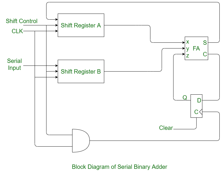
But i'm not sure if this is the right way to perform this design, i would like to keep as much close i can to the diagram i posted. At high level i would say probably internally should be even a counter that probably keep track of when all the bits are being processed.
#Serial adder vhdl how to
The internal architecture confuse me a lot since actually i don't know how to behave in the synchronization stuff. Z : out std_logic_vector(n - 1 downto 0)) Port(x, y : in std_logic_vector(n - 1 downto 0) I'm not sure however how the whole entity for the adder should be designed i would attempt with something like entity adderSerial is Register and flip flop should be updated and shift for every clock cycle, the full adder is combinatorial so it is ok. I would start with a register (n bit) a full adder and than a flip flop as basic component. Since i'm not skilled enough in design with clock (except some silly flip flop i've found on the web, and similarly a register, where the design is pretty much the same) i have some problem in the design.
#Serial adder vhdl serial
I've a design problem in VHDL with a serial adder.


 0 kommentar(er)
